6ft Nano / Build guide
Follow the Nano build
See how the hull comes together, with workshop photos, component diagrams and an overview of the assembly stages.
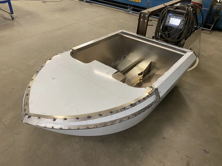
What to have ready
Have the packing list, assembly drawings, selected interior parts and donor details beside the workbench. Set out measuring tools, clamps, a flat support surface, aluminum preparation tools and suitable welding equipment before you start.
For the Nano’s aluminum fabrication, Sitka specifies 5356 filler. Pulsed MIG is used in the workshop examples. Set up and prove the welding process on matching material before working on the hull, with clean joints and suitable shielding gas.
Before making permanent changes, identify the parts, reference measurements and weld sequence for your Nano. If a drawing or part is unclear, send Sitka a labeled photo before cutting or welding. Use the document checklist to get ready.
Plan the donor installation before hull assembly, then mock it up again before permanent mounting and routing. The workshop checklist and complete systems list cover the equipment and systems. New to the terms? See the plain-language glossary.
1. Prepare the kit
Lay out the parts and check them against your order. Some pieces may be wrapped together or packed inside cardboard, so check the packaging before recycling it. Group the parts by assembly and keep identification marks visible.
Remove protective film from every area affected by welding heat; retain it only on surfaces clear of that work. Set up a stable workbench with space to support and turn the hull. Check how the panels fit and align before making long welds.
Use suitable protection for sheet-metal handling, grinding and welding. Check the equipment and skills needed for each job before you start; arrange help with any work you cannot complete and verify yourself.
- Identify the bottom, paired side panels, chines, transom pieces and internal supports. Group the smaller bow, cover and tank-seat components separately.
- Preserve the panel identification marks while preparing the joining edges. Check that the inside corners of the adjoining panel edges meet as shown in the diagram before placing tacks. Use the specified joint preparation; do not trim an edge just to hide a fit problem.
- Read ahead to the next assembly so you know which surfaces must remain accessible.
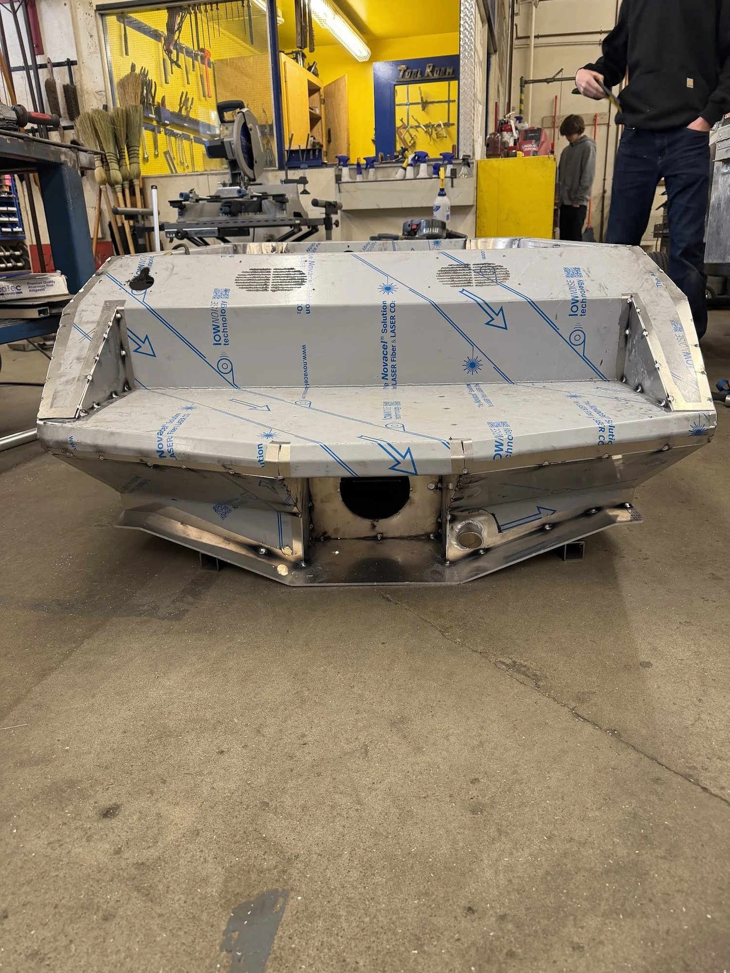
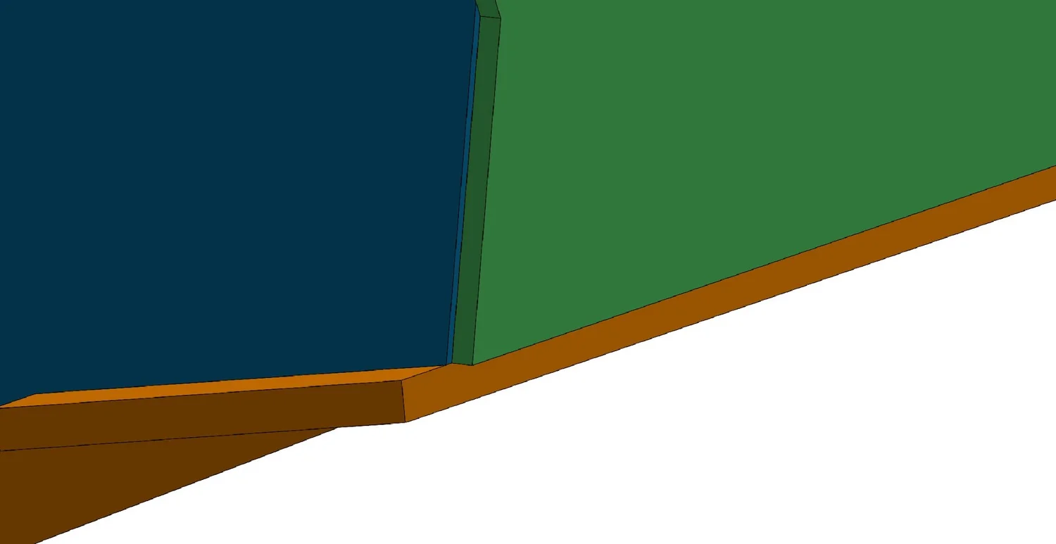
2. Build the smaller assemblies
Start with the bow and dash, engine cover and tank-seat components included in your configuration. Working through these assemblies helps establish how the pieces locate and fit together before you move onto the hull.
Lay out the matching parts before welding. Plan access to internal joints as each assembly closes in. For fuel-system work, check the skills, equipment and testing requirements before starting.
Bow and dash
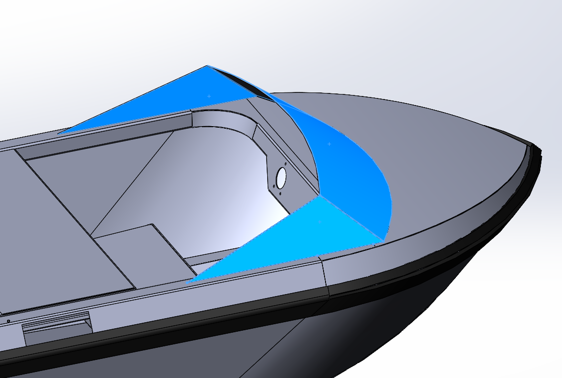
Lay out the curved bow pieces and dash, then bring the adjoining edges together progressively. Check the assembled shape against the hull before the final joining work.
Engine cover
Place the main cover panel, locate the gusset (the reinforcing support) using its locating notches, and add the side panels and side fillers. Check the cover’s fit and the clearance it will need over the engine before completing the welds.
Tank-seat components
If selected, lay out the tank body, sides, internal supports, top and fittings as one assembly. Plan the access needed to weld internal supports before closing the tank. Fabricate and test the fuel tank and connections only if you have the relevant marine fuel-system skills and equipment. Otherwise, use a marine fabricator for that part of the build.
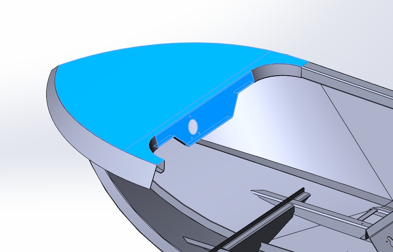
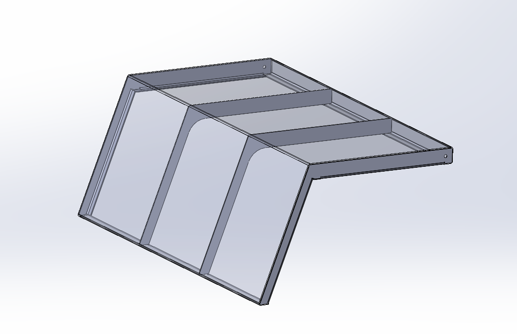
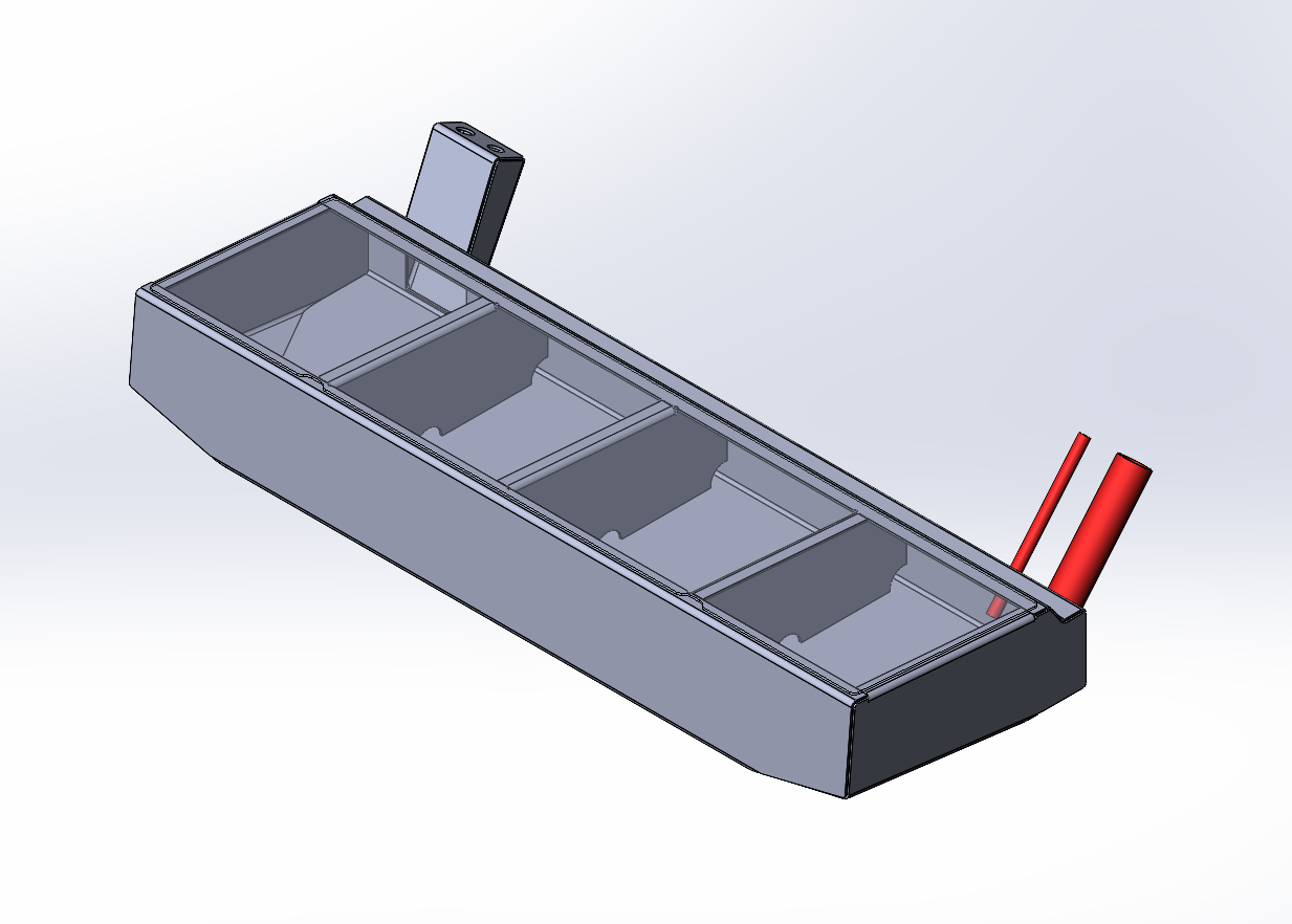
3. Assemble the bottom and internal structure
Bring the bottom, reverse chines and internal supports together while the hull is still open. Keep it supported and check the adjoining parts as you work.
- Start on a flat, stable work surface and secure the rear of the bottom against movement. Bring the bow panels upward using the bottom guide curve, the shaped reference piece that sets the bow rise. The bow is curved; do not try to flatten the whole bottom onto the bench.
- Fit the reverse chines from the rear toward the bow. Use the adjoining panels to check their angle as the hull takes shape.
- For the pump-box arrangement shown, fit the pump plate and side pieces together; the side pieces hold the plate square to the bottom. Then fit the transom bottom wings.
- Prepare the stringers and crossmembers before fitting them into the hull. Use their locating notches and adjoining pieces to check placement. Check the drawing’s reference measurements, including the spacing between chines and the distance from the intake opening to the bow reference, before adding the sides. Measure from the specified points each time.
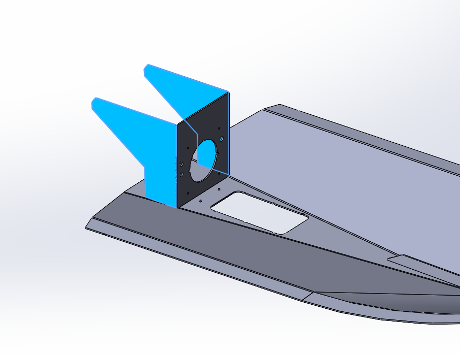
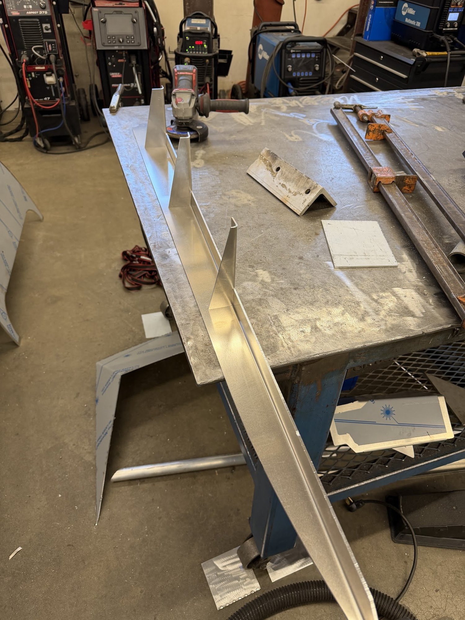
4. Fit the sides, bow and swimdeck
The sides connect the bow and rear structure. Keep the upper panels and swimdeck at hand so you can check the adjoining edges before welding.
- Fit each side from the bow toward the stern, checking its bottom edge against the chine and its upper edge against the adjoining pieces.
- Bring the bow and dash into place, working progressively along the curved joints. Recheck the fit if a panel needs excessive force.
- At the rear, finish the joints that the swimdeck will cover before tacking its upper panels in place. Keep heat input controlled while access is limited.
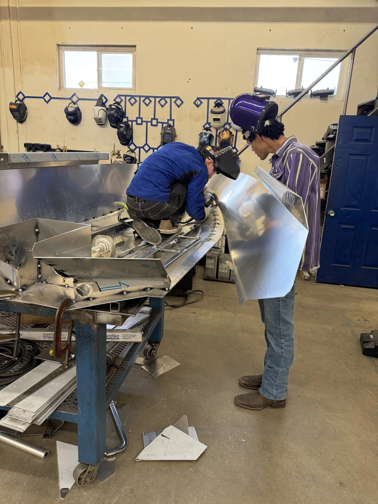
5. Weld the hull and add the windscreen
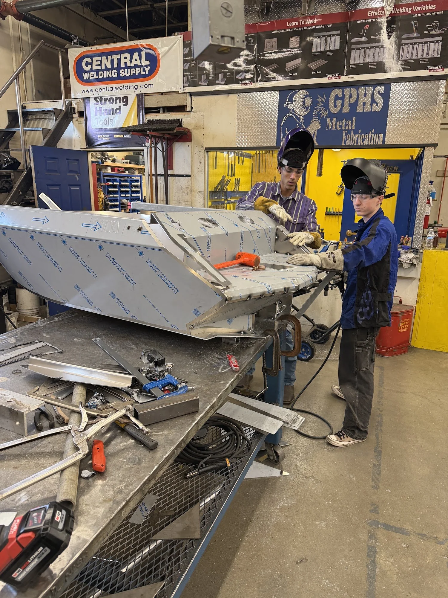
Complete the main hull welding before adding the windscreen so the shell is easier to support and turn. Then fit the windscreen and cap and finish the exposed edges.
Control heat and keep checking the shape
Check the tacked hull before starting the main welds. Work in short sections and move around the hull so heat does not concentrate in one area. Support and turn the boat to reach each joint comfortably; allow it to cool when heat builds up.
Weld preparation, joint geometry and access vary around the hull. Use the prescribed sequence for each joint and inspect starts, stops and adjoining welds as you work. Resolve distortion or weld defects before adding the windscreen and finishes.
Recheck the hull before the main welds
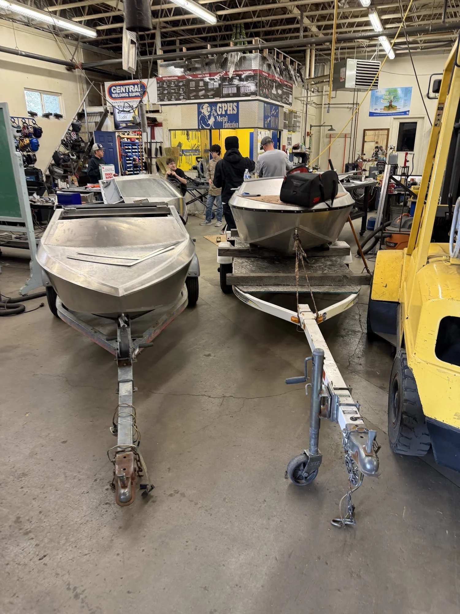
Use the assembly drawings to check the bottom, transom and upper panels for alignment and twist while the hull is still tacked. Record the reference measurements and recheck them as welding progresses. If an adjoining panel no longer fits, resolve the alignment before adding more welds.
Deburr accessible edges before later assemblies restrict access. Finish only the welds and surfaces identified for dressing; do not grind a structural joint thin to make it look smooth.
6. Fit the intake grate
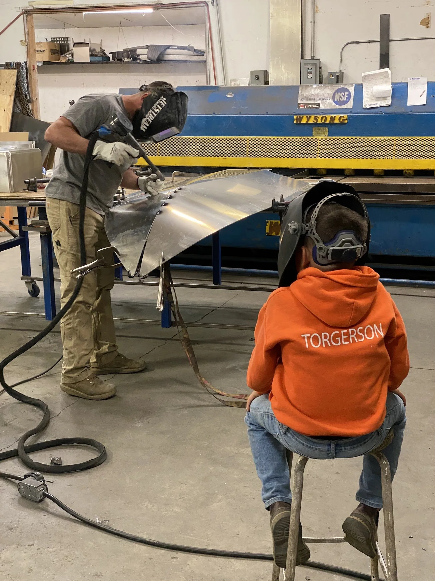
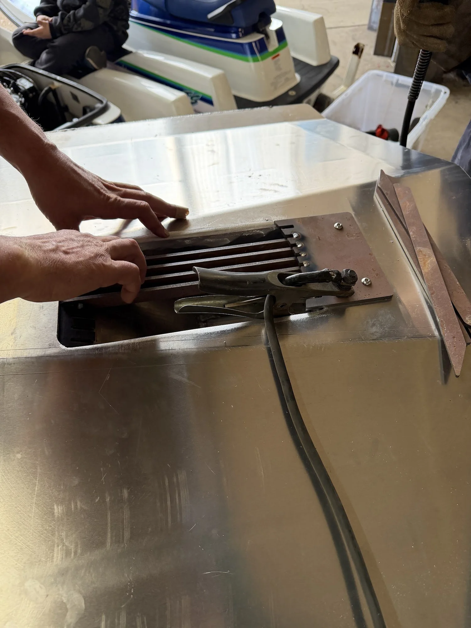
Fit the rear grate piece and locate the front section. With the pieces positioned, tack the bars together. Remove the grate from the boat to complete its welds, then check the fit when it is reinstalled.
Check the adjoining parts before sealing
Dry-fit the intake, pump adapter and adjoining hull parts as a complete arrangement. Identify the fastener, steering-cable and cooling-water passages before drilling or sealing anything. If hull protection is selected, account for its thickness and edge fit at the intake using the matching installation details.
Follow the component instructions for surface preparation, sealing, tightening and cure time. Keep the grate removable and inspect the completed joints before the installation is covered.
7. Mock up and fit the drivetrain
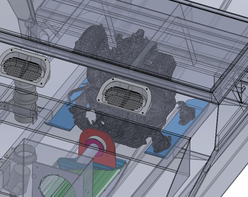
Set the engine position from the complete pump and shaft layout. Keep exhaust clearance, cooling connections and service access in view throughout the installation.
Use the donor jet ski guide to gather the information needed for your setup. Mock up the engine, pump, exhaust, tank and supporting equipment together before making permanent mounts or cutting hoses and cables. Install fittings that would become inaccessible before lowering the engine into its final position.
- Trial-fit the pump, bearing carrier and driveshaft as one assembly before setting the engine position.
- Bring the engine into alignment with the coupling and shaft. Check free movement and alignment using the component manufacturer’s method; do not use mounting bolts to pull a misaligned assembly into place.
- Check exhaust, cooling, cover clearance and access to service items before marking the mounts for final installation.
- Complete the drivetrain mounting, then recheck alignment and the shaft-seal arrangement after everything is secured. Finish the supporting-system connections in the next stage.
Work through the completion and first-launch checks after rigging. Keep photos and test results with your parts list.
Prove access before final assembly
A mock-up is a trial installation, not the final fastening. Check whether the bilge pump, aft cable connections, ventilation ducting or other fittings need to go in before the engine blocks access; remove the engine using your planned lifting arrangement if those jobs need more room. With the engine and cover trial-fitted, confirm that you can reach the shaft seal, mount fasteners, oil-service points and hose clamps, and remove the bilge pump for cleaning.
Plan the mount adjustment and alignment tools required for your selected drivetrain. Recheck alignment after the mounts are secured, using the component procedure.
8. Install and check the supporting systems
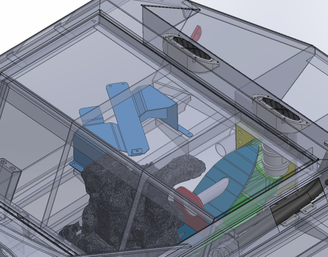
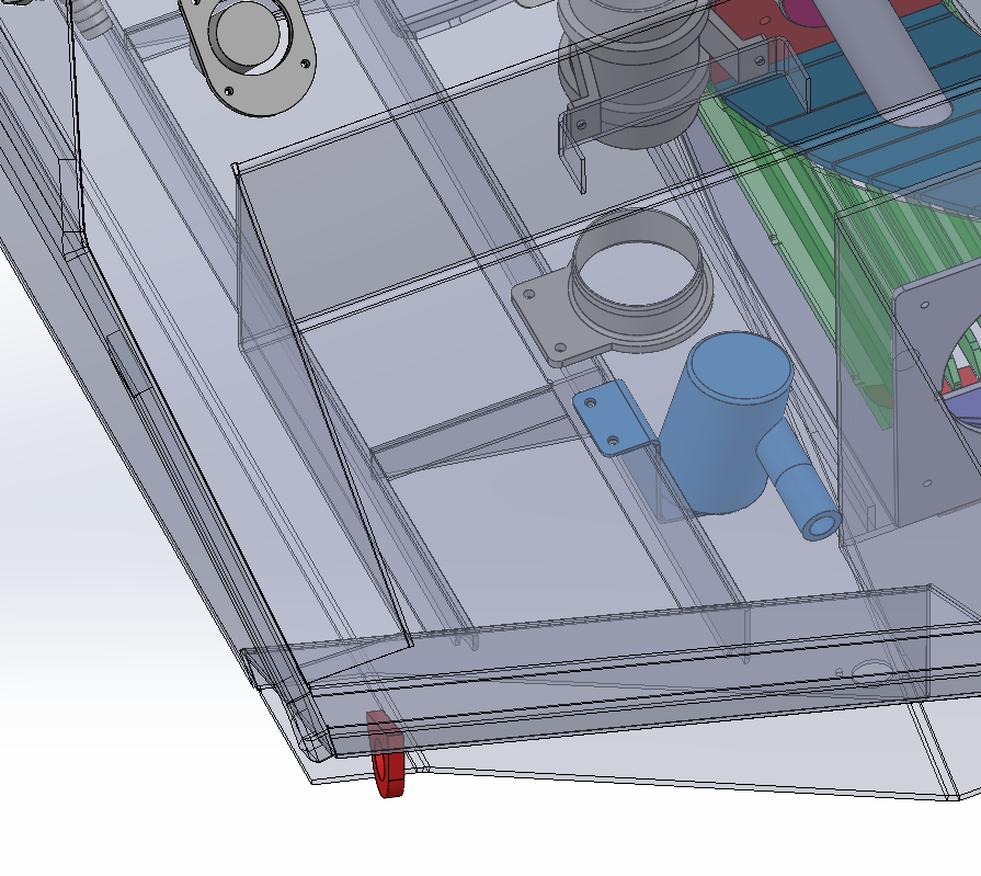
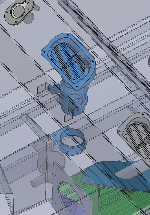
Use the drivetrain mock-up to set the final routes for steering, fuel, cooling, bilge, ventilation and electrical systems. Work from a complete parts list. Identify the included mounting points, the parts you can reuse and the components you still need to purchase.
The sample parts list organizes selected components by system. Add the battery, wire, hoses, fittings and any other items required for your own setup.
Lay out the routes before cutting hoses or cables
- Position the helm and its support, then plan the steering-cable route and nozzle connection. Check the required length and travel.
- Locate the bilge pump and its discharge fitting, with access to service the pump and inspect the hose connections.
- Lay out the blower, vents and ducting together. Keep the intended airflow path clear of interior panels and stored equipment.
- Plan the fuel fill and vent connections, battery and protected wiring routes. Leave room to reach clamps, terminals and switches after the cover is fitted.
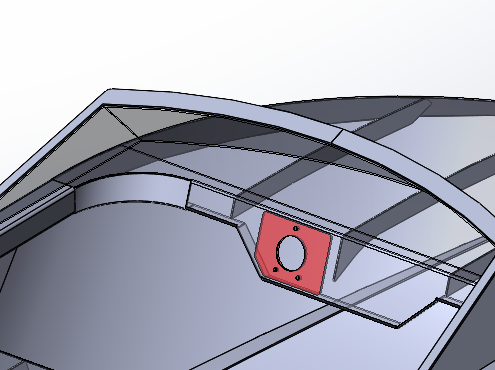
A pre-cut hole or mounting point does not include the device that fits it. Use the complete systems checklist to account for the equipment, mounting hardware and connections.
Prepare for first launch
Keep the interior accessible until the required weld, leak, control and system checks are complete. Record the results and resolve any faults before launch; get specialist help for checks you cannot complete or assess confidently.
Use the workshop and first-launch checklist to move from an engine-off inspection to a short, controlled water trial. Keep the component manuals, wiring notes and test record with the boat for future maintenance.